Stair Traversal and Exploration Platform

The Project
Developing a small-scale humanoid bi-ped that can walk, climb obstacles, and navigate in an environment intelligently.
The Plan
After talking with people in the humanoid industry, the plan laid out for the project was to get the simplest demonstration ready as a proof of concept and iteratively build complexity and expertise on top of that.
Phase 0
-
The goal was to design a 6-DOF walking robot
-
The first Concept was designed to jumpstart the process and see what exact gaps I had in the knowledge.
-
Each leg was designed for 3 Degrees of Freedom
-
For the Knee Joint, a parallel linkage Mechanism was considered so that the Feet would always stay parallel to the ground. This would allow me to not care about the DOF for the feet.

Learnings after review with people in the industry
-
Minimize complexity across the board. Just get to the most basic demo
-
Get Clarity on further questions
-
Can you even make a bipedal robot without the top half that is stable and can actually, walk?
-
Why do you need 6 DOF?
-
Can you design a robot that can walk with 2 DOFs?
-
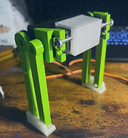
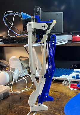
Phase 1 ( 2 DOF Robot )
Key Goals
-
Design a 2 DOF walking robot that can walk on flat ground.
-
Understand the underlying physics of the mechanical system and build complexity gradually
-
Understand why exactly you need every Degree of Freedom

Problems and insights
-
there needs to be a propelling force that needs to be exerted in the backward direction for the robot to walk in the forward direction. with the servos placed in the directions given. there was little to no exerted force in the backward-forward direction. this leads to the robot moving in its place.
Solutions tried to get the robot to walk
-
For the robot to walk, one solution I could work with is to manipulate the surface on which the robot walks to create a differential in traction. ( did not work )
-
need a surface that can slide forward easily but can’t be slid backward easily. maybe, design new boots for the robot.(did not work)
-
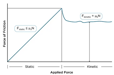
Using the difference between kinetic friction and static friction move the leg forward faster and drag it back slower. (Works. the robot moves forward and can turn 90 degrees)
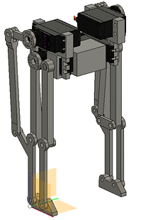
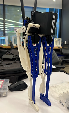
Phase 2 ( 4 DOF Robot )
Key Goals
-
Design a 4 DOF walking robot that can walk on flat surfaces and climb a small obstacle
-
Write a Robot URDF
-
Generate a walking trajectory for the robot
-
get started with the simulation

Learnings
-
servos used in this prototype cannot generate feedback, not allowing me to apply a PID controller for the walking gait cycle
-
generation of the walking Gait mechanism becomes a trial-and-error method as I have to adjust the code by visually seeing the output of the gait.
-
variability of the servos combined with the structure. it makes the whole body have backlash. That gives me less control as the backlash error keeps adding up as the number of joints increases.
-
I should design a joint that does not increase friction proportional to the tightness of the joint.
-
variability of the servos combined with the structure, makes the whole body have backlash. that gives me less control as the backlash error keeps adding up as the no. of joints increases.
4 DOF iteration 2
Key Goals
-
Design the robot 4DOF walking robot
-
better designed links and joints
-
It should be a mobile robot that can be controlled remotely
-
battery management system onboard
-
The robot should not have loose wirings or a power connection ( should run on an onboard battery )
-
COM tracking and onboard IMU
-
Servo motor sizing with position feedback
-
Generate Gait for a 4 DOF robot

-
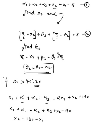
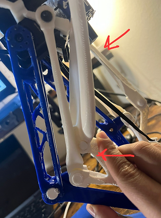
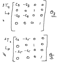
each leg is designed as a 5-link mechanism embedded within a 2R mechanism. that introduces a higher layer of complexity into the whole design. solving it took some time but we solved the modal as a mathematics function. here is the full breakdown of the solution
-
this puts constraints on the 5link mechanism and recalculates the inverse kinematics of the whole mechanism.
Inverse Kinematic Solution
1)

2)
Simulation Progress
-
We wrote a URDF ( universal robot description format ) for our robot
-
imported that URDF file into the gazebo physics engine for simulating the physics of the robot
-
we setup the environment in a way that allows us to predict what happens to the robot
Problems
-
after solving kinematics, we made the robot follow different trajectories. after a lot of trial and error on getting the robot to walk. we discovered a singularity in the design.

-
The location of the singularity was at the pose of the robot which was necessary to achieve a gait cycle.
-
the robot was falling quicker than we could move the foot from s single-supported phase to a double-supported phase. this meant that the the distance between the feet was higher than what the system could handle making it topple quickly.
-
We had 2 options at this point. Re-design the 4DOF system to figure out gait or focus on the 6DOF system. ( 6DOF can also act like a 4 DOF system if we lock 2 actuators ) and decided to focus on the 6 DOF system as that doesn't have this type of singularity in the design.


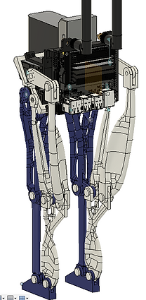
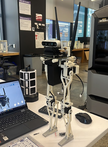
Phase 3 ( 6 DOF system )
Key Goals( including all the previous key goals )
-
Design the robot 6DOF walking robot
-
links and joints designed without singularity in the required workspace of the robot
-
the robot should have mechanical capabilities to climb 3.5 in stairs. ( half of what's required to climb a full scale which is 7-8 inches )
-
foot design to accommodate lateral stability and with contact modeling
-
IntelliSense Camera onboard for getting the point cloud of the stairs.
-
Algorithmic design to execute the task of stairclimbing for Perception, Gait Generation, and Controls.

Forward and Inverse Kinematics


Control Analysis of the Structure
-
To design the Ideal gait cycle and control algorithms for our robot for walking we needed to understand the boundaries of our system. we plotted the bode plot for a single leg while keeping the knee locked.
-
Plotting this gave us a measure called the bandwidth frequency of the system which came out to be 0.27Hz
-
That tells us that the minimum time-period of a gait cycle can be 1/bandwidth frequency
Simulation to Real
-
We implemented a closed-loop inverse kinematics algorithm. Here, we used the Newton-Raphson method to iteratively calculate the desired joint angles that would achieve the given position
-
We modeled the robot in the universal robot description format, and we used Pinocchio and its ancillary libraries to help us with the inverse kinematics
-
Pinocchio is chosen for its speed, efficiency, and versatility, as it’s at the heart of the optimal control library, crocoddyl.
-
We modeled the robot in 2 different ways, first as a serial manipulator from one foot to the other. Second, from the torso downwards to each foot
-
We used the latter for our problem, as it produces more realistic motion in our current implementation. Once we load our URDF file and associated meshes, we create various data structures along with our visual and collision models to use for display and collision check
-
We then iteratively find the final joint configurations using the Jacobian. Here two key “modifications “ are used.
-
First, we premultiply the jacobian with the negative of the log derivate of the transformation matrix to map velocities in the right frame- similar to an adjoint map
-
Second, a damped jacobian, to provide numerical stability close to singularities
-
-
Lastly, there are collision checks and the imposition of joint limits.
-
We then map from joint space to actuator space to achieve motion in the real world
Phase 4 ( 10 DOF system )
-
The team is working on multiple fronts
-
the 6DOF has been designed, and currently, we are solving walking without any supports
-
We're reviewing and finishing the Design 5
-
Problems regarding the firmware and power electronics for iteration 5. The robot is designed on a 24V architecture
-
Foot design to accommodate lateral stability and with contact modeling for 6 DOF system
-
Algorithmic design to execute the task of stairclimbing for Perception, Gait Generation, and Controls for 6 DOF system

10 DOF System Dynamic Modal Calculations


Fabrication Run for 10 DOF
The mechanical team had a 3-week deadline to fabricate 86 aluminum parts and assemble the 10DOF robot. Without wasting a second, we commandeered the CNC tormach 440 and 770 machines accessible in our university, divided all the parts, and started fabrication parts by ourselves. Buying 16,00,000 mm^3 of 6061 Aluminium, and burning through 21 cutting tools we learned key principles in topics like design for manufacturing, assembly consideration, and tolerances.


Achievements
-
Achieved Static walking within 9 months of starting the project
-
Raised 5000$+ for the projects through grants and crowdfunding
-
Accepted to showcase at the IHMC Dynamic Walking Conference 2024 Pensacola Maimi
-
Awarded 1000$ extra in travel grant to attend the Dynamic Walking Conference
-
Invited to give a talk at the Disruptive Medical Technologies hosted by NYU
-
Machined and Fabricated 86 aluminum parts within 3 weeks using 1 milling machine
Fundraising and the Team
-
As we started working on the 4 DOF system, I realized the complexity of the project is scaling up and we need more expertise in the team. Moreover, we needed Funds to keep the project going.
-
After talking to a huge pool of people from the university I brought the right type of people together who are driven enough to work on challenging problems.
-
We have raised 5000$ until now for the project through the NYU Makerspace funding showcase and crowdfunding which enabled us to build this project.
-
Watch our interview with NYU!


Meet the team

Abhinav Kumar
Team Lead

Pranay Gupta
Controls Engineer

Aditya Tiwari
Robotics Software Engineer

Soorya Narayanan
Mechanical Design Engineer

Tasleem Khan
Fundraising and Marketing
Grad Students from Gait and Manipulation Class

Archit Jain
Gait and Manipulation


Zhiquan Cao
Simulation
Abishai A
Simulation